This page describes the theory behind motor mixing for multirotors. The reader will be familiar with how to come up with mixer tables for any motor configuration. Pseudo-inverse technique is used.
A typical control architecture for multirotor vehicles is as follows:
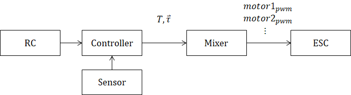
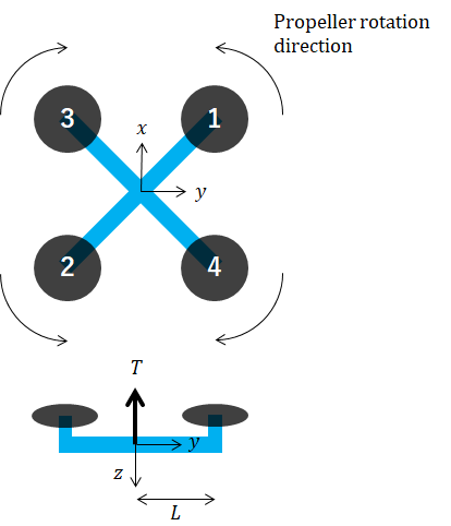
The controller outputs desired thrust, T, and roll/pitch/yaw torques, τ. Then the mixer converts those values to individual motor commands. For example, let an X-configuration quadrotor of the following form:
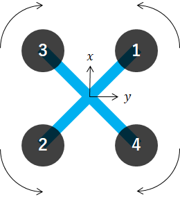
Arrow indicates the direction of rotation of the propeller when looking down at the quadcopter from above. Note that the clockwise propeller causes a counter-clockwise moment on the quadcopter. The mixer algorithm for this drone is as follows:
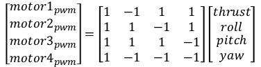
motor1_pwm = thrust - roll + pitch + yaw
motor2_pwm = thrust + roll - pitch + yaw
motor3_pwm = thrust + roll + pitch - yaw
motor4_pwm = thrust - roll - pitch - yaw
We are using front-right-down (roll-pitch-yaw) coordinates and thrust is in up direction. The above math can be rewritten in matrix form as,
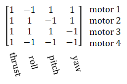
The matrix in the middle with 1s and -1s is called a mixer table. It is an N-by-4 matrix where N is the number of rotors. It is possible to guess this matrix just by intuition but it soon becomes complicated when there are more than 4 motors. The following sections explain a method to mathematically determine this matrix. This problem is part of a broader field called "control allocation".
To simplify things, let us first consider the 2D case. Given T (thrust) and τ (pitch torque) and L (arm length), the problem is to determine F1 and F2 (forces from the right and left motors respectively).
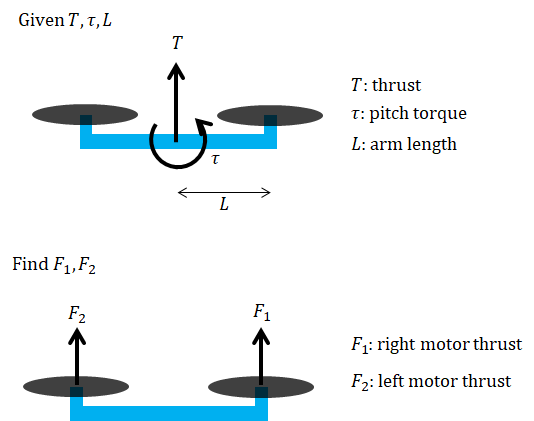
Summing the forces and torques, we get:
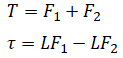
In matrix form:
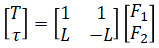
Solve for the individual motor thrusts by inverting the matrix:
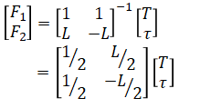
This can be normalized by separating the matrix:
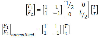
So the motor mixer table is given by,
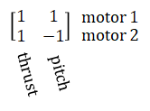
So the final algorithm is,
motor1_pwm = thrust + pitch
motor2_pwm = thrust - pitch
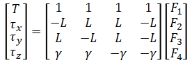
Now let us consider a 3D case. We will use X-configuration quadrotor again as we already know the answer.
Summing the forces and torques, we get:
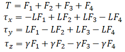
γ is rotor drag to thrust coefficient given by,
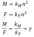
where n is rotor rotation speed, kT is thrust coefficient, and kM is moment coefficient. kT and kM are only dependent on rotor geometry (and so is γ).
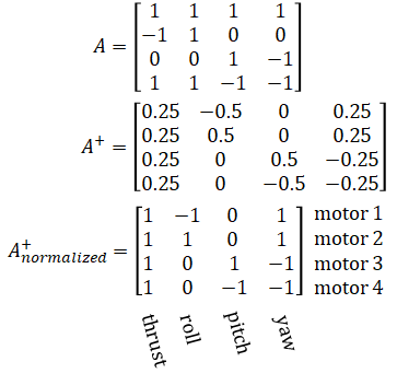
In matrix form,
Solve for the individual motor thrusts by inverting the matrix
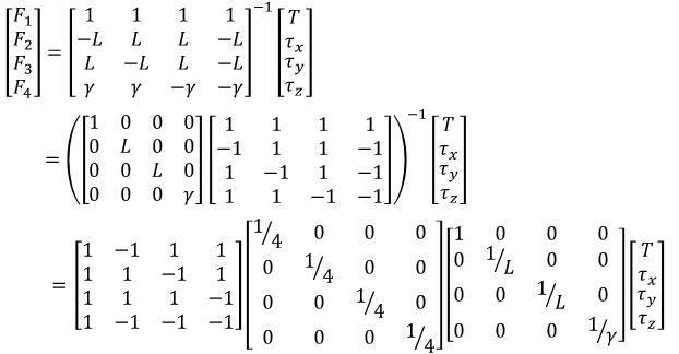
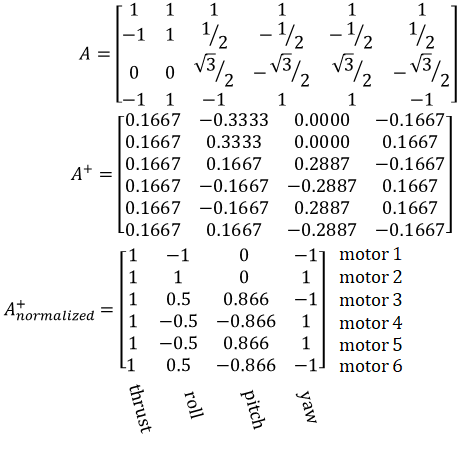
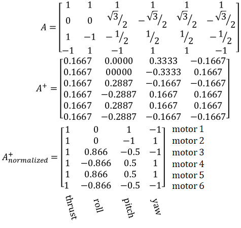
The normalized mixer table is:
Given N rotors positioned at (x1, y1), (x2, y2), ... (xN, yN), the general from is:
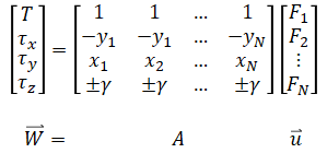
where +γ is for propeller in CCW rotation and -γ for propeller in CW rotation. The solution to the above equation is:

where + is Moore-Penrose pseudo-inverse. A python script to solve the above is as follows:
import numpy as np

# XYZ are in front-right-down coordinates
# rotors = [
#     Position Prop-Direction
#    [ x1, y1, 'CW'/'CCW'],
#    [ x2, y2, 'CW'/'CCW'],
#    [ x3, y3, 'CW'/'CCW'],
#    ...
# ]

# Quadrotor-X
#    3   1
#      x
#    2   4
rotors = [
    [ 1,  1, 'CCW'],
    [-1, -1, 'CCW'],
    [ 1, -1, 'CW' ],
    [-1,  1, 'CW' ]
]

def normalize(B):
    scale = np.abs(B).max(axis=0)

    # Same scale on roll and pitch
    scale[1] = max(scale[1], scale[2])
    scale[2] = scale[1]

    return B / scale

gamma = 1 # Drag to thrust coefficient

# 4 x N matrix where N is the number of rotors
# Row 1: thrust
# Row 2: roll torque (x)
# Row 3: pitch torque (y)
# Row 4: yaw torque (z)
A = np.array([
    [1] * len(rotors),
    [-i[1] for i in rotors],
    [i[0] for i in rotors],
    [-gamma if i[2]=='CW' else gamma for i in rotors]
])

B = np.linalg.pinv(A)

print(A)
print(B)
print(normalize(B))
Let, L = 1, γ = 1
c = np.sqrt(3) / 2
rotors = [
    [ 0,  1.0, 'CW' ],
    [ 0, -1.0, 'CCW'],
    [ c, -0.5, 'CW' ],
    [-c,  0.5, 'CCW'],
    [ c,  0.5, 'CCW'],
    [-c, -0.5, 'CW' ]
]

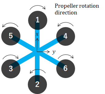
Let, L = 1, γ = 1
rotors = [
    [ 0,  1, 'CCW'],
    [ 0, -1, 'CCW'],
    [ 1,  0, 'CW' ],
    [-1,  0, 'CW' ]
]
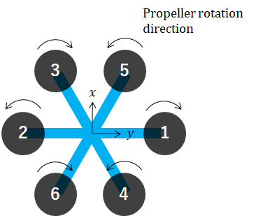
Let, L = 1, γ = 1
c = np.sqrt(3) / 2
    rotors = [
    [ 1.0,  0, 'CW' ],
    [-1.0,  0, 'CCW'],
    [-0.5, -c, 'CW' ],
    [ 0.5,  c, 'CCW'],
    [ 0.5, -c, 'CCW'],
    [-0.5,  c, 'CW' ]
]
Often times γ is not known so it is simpler to scale roll/pitch and yaw separately. In such case, the commands from the controller is no longer in valid SI-units (e.g. N and Nm).
The output of the mixer is fed to the ESC as pwm duty. In our calculation the output of the mixer is force whereas the ESC accepts rotational speed of the rotor. The force needs to be divided by the thrust coefficient and square rooted. However this is often not done.