Accelerometer Calibration
This page describes a method for calibrating low-g (~3g) three axis MEMS accelerometers.
The method involves taking measurements at six different orientations, and then,
solving for the 12 calibration parameters using least squares method.
This calibration will account for the sensor's zero-g bias, cross-axis interaction,
sensitivity changes, and package misalignment.
Example and limitations are also provided.
Why calibrate?
Accelerometers need to be calibrated because offsets, axis misalignments, and
sensitivity changes are introduced after production. These are caused by:
- Temperature changes
- Aging
- Thermal stresses introduced in soldering process
- Mechanical strains from
- The sensor package as a result of mounting to the PCB
- PCB mount holes or screws
- Other components placed close to the sensor
Without calibration, the device will appear tilted when it really is not, and
give incorrect acceleration readings.
Calibration Model
We assume that raw measurements (rx, ry, rz) can be converted to calibrated
values (cx, cy, cz) by multiplying a 4-by-4 matrix:
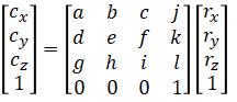
This is a 3D affine transformation which means that it does linear
transformation (rotation, shear, scaling) and translation (offset).
Translation
This corrects for "0g-offset" (or "0g-level") which is the accelerometer reading at 0g.
0g-offset is also called "constant bias", "bias error", "long term bias", "measurement bias" or just "offset".
An ideal accelerometer has offset value 0 because it should read 0 acceleration
when there is no acceleration. In reality, the device outputs a small non-zero value
even at 0g, so the offset must be subtracted when the device is being used.
This value changes with temperature and the amount it changes is
usually denoted in the datasheet as "Zero-G Level Change vs. Temperature".
This term should not be confused with the displacement of the sensor from
the center of gravity of the device the sensor is mounted on.
Scale
This compensates for sensitivity of the device.
An ideal accelerometer has scale value 1 (meaning that the sensitivity denoted
in the datasheet is correct).
This value changes with temperature and the amount it changes is usually
denoted in the datasheet as "Sensitivity Change vs. Temperature"
Skew
This takes care of the non-orthogonality of MEMS elements in each of the axis directions.
Sometimes referred as "Axes Misalignment" and "Cross Coupling".
Also related to "Cross-Axis Sensitivity".
Rotation
This accounts for the misalignment of die positioning on the package substrate.
This corrects any package misalignements between accelerometer axes
and device body axes (sensor board).
In summary, calibration method using this model will
compensate for both the device cross-axis sensitivity and
the misalignment between the accelerometer sensing axes and the board axes.
Calibration Method
Calibration parameters, a to l, are determined by least squares:
(eq. 1)

(eq. 2)

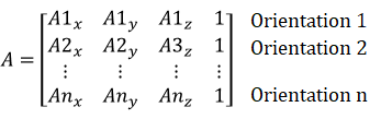
where
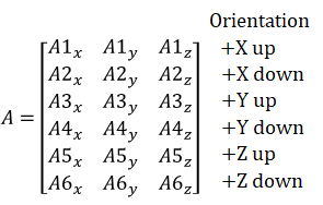
- A: (nx4 matrix) raw measurements collected at predefined orientations
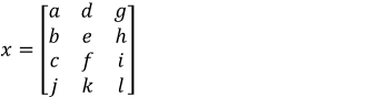
- x: (4x3 matrix) calibration parameters (unknowns)
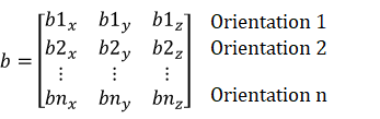
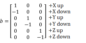
- b: (nx3 matrix) desired calibrated values for each of the orientations in A
Linear transformation has 9 degrees of freedom and translation has 3 degrees
of freedom, so it has 12 degrees of freedom in total (12 parameters: a to l).
As a result, at least 12 equations are needed to solve for the 12 unknowns.
1 orientation results in 3 measurements (x, y, and z) so the device needs
to be in at least 4 different orientations for the equation to be solvable.
Steps
The following describes six point calibration:
- Collect 5 to 10 seconds of raw data while the sensor's +Z axis is pointing up.
- Repeat for the other 5 faces and record them in each row of A matrix:
- Solve for x using (eq2) where b is as follows:
Once calibration parameters, x, are solved, raw measurements can be converted to
calibrated parameters using (eq1)
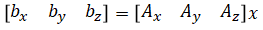
where [Ax Ay Az] are raw measurements and [bx by bz] are calibrated values.
Calibrated values are in units G.
Limitations
- Low-g accelerometers only
Gravity is used as the reference, so this method works
for low-g accelerometers (~3g) but not for high-g accelerometers (~200g).
A larger controlled acceleration is needed to calibrate high-g accelerometers.
- Location dependent
Gravity varies by 0.7% over the Earth's surface due to Earth's rotation,
altitude, and the Earth not being a perfect sphere. For example,
- Sea level at the north pole: 9.832 m/s/s
- 5895m summit of Mount Kilimanjaro near the equator: 9.763 m/s/s
Calibration method described here will cancel out the gravitational field
and assume whatever the gravitational acceleration is at the calibration site
to be "1g". If, however, an absolute estimate in m/s/s
is needed, then the gravitational field at the calibration site must be recorded.
This value can then be multiplied to convert from "1g" to m/s/s.
- Temperature dependent
MEMS elements are sensitive to temperature changes. Calibration parameters are
needed for every temperature that might arise in practice. IMUs usually
contain a temperature sensor, so this technique can be extended to include
temperature dependence by performing calibration at two or more temperatures
and interpolating the fitted calibration parameters to the actual temperature.
Also note that two accelerometers of the same product may have different
temperature characteristics.
- Other considerations
- Numerical Instability
Solving least squares involves computing the matrix inverse.
Check to make sure the determinant is not close to zero.
- Outliers
Least squares method is prone to outliers.
Detect outliers and redo calibration.
- Vibrations
Accelerometers are spring-damper system (underdamped second order
system) with a natural frequency and damping ratio. Accelerometer measurements
may saturate if there is constant vibration near resonance (like in a drone).
- Drift
This is also called bias instability. Accelerometer value slowly changes even
though the device is at rest and temperature stays constant. This is not to be
confused with drift due to integration. Drift can be corrected by estimating
it online using other sensors like GNSS.
- IMU location
If the accelerometer is positioned away from the center of gravity of the device,
acceleration experienced by the accelerometer will be different than when it
is placed at the center of gravity.
- Forces on circuit board
MEMS elements are sensitive to forces acting on the circuit board,
like a dangling connector.
- Some IMUs simply stop responding after a while and need to be reset.
This is critical for things like drones.
Sources
- ST AN4508 Parameters and calibration of a low-g 3-axis accelerometer
- NXP AN4399 High-Precision Calibration of a Three-Axis Accelerometer
- NXP AN3916/AN4069 Offset Calibration of the MMA8450Q
- NXP AN3447 Implementing Auto-Zero Calibration Technique for Accelerometers
- 3-Axis Accelerometer Calibration Based on Intrinsic Properties
https://www.nist.gov/programs-projects/dynamic-mechanical-metrology-acceleration-force-and-acoustics/3-axis-accelerometer
- How to Improve the Accuracy of Inclination Measurement Using an Accelerometer
https://www.analog.com/en/analog-dialogue/articles/how-to-improve-the-accuracy-of-inclination-measurement-using-an-accelerometer.html
- LaValle "Virtual Reality", Cambridge University Press, 2016