This page describes how the differential drive mechanism of the DIY robot vacuum works. Below is a video showing the robot moving back and forth in a zig-zag pattern. No encoders are used. This is an open-loop control with motors commanded to turn at predefined timing.
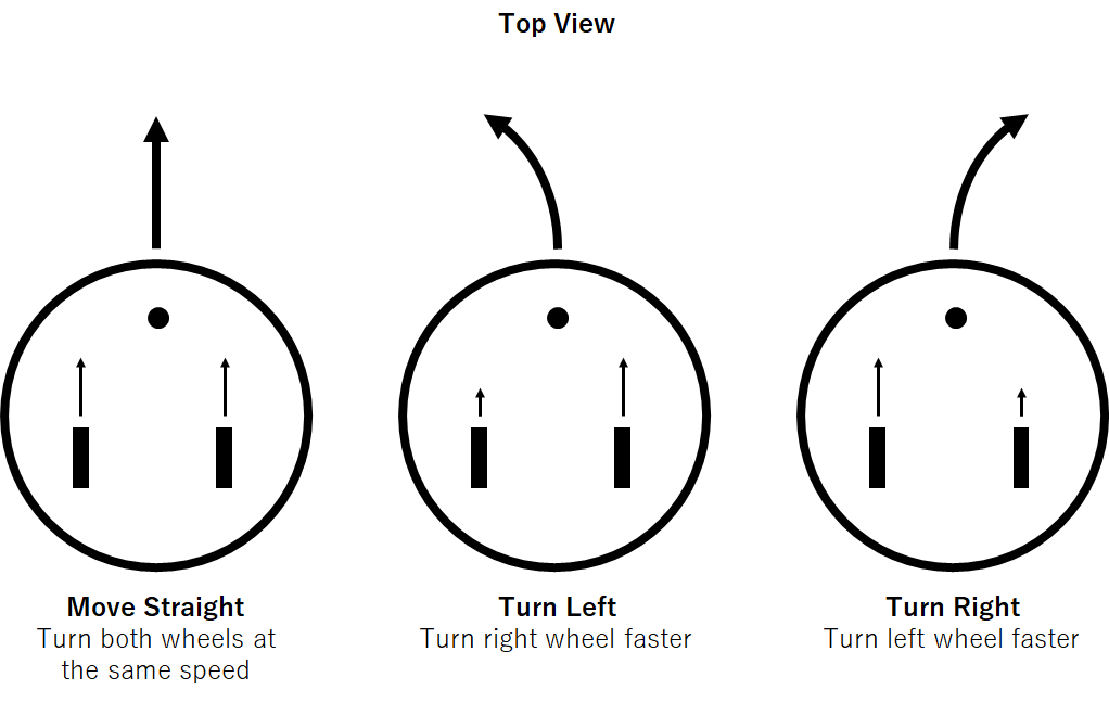
The robot has two wheels that can be controlled to rotate at different speeds and directions. The wheels are driven by DC motors. The robot moves in a straight line when the two wheels are turning at the same speed. The robot turns when the two wheels rotate at different speeds. This mechanism is called “differential drive.”
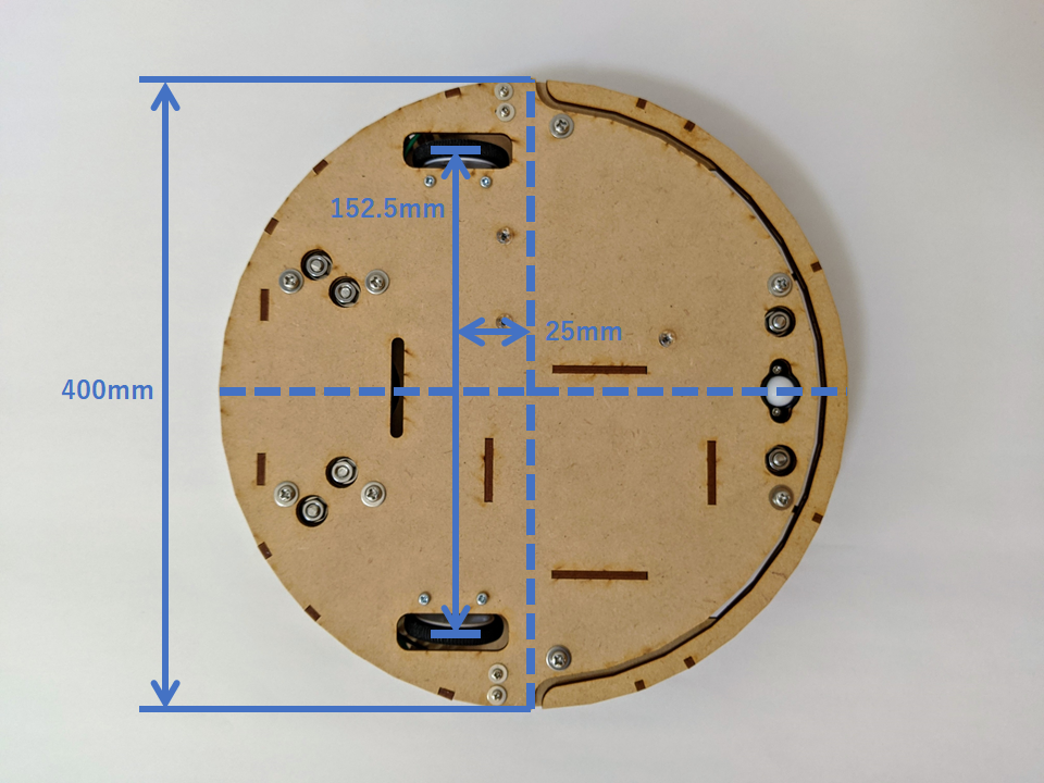
The distance between the two wheels is 152.5mm. The midpoint between the two wheels is 25mm offset from the center of the robot.
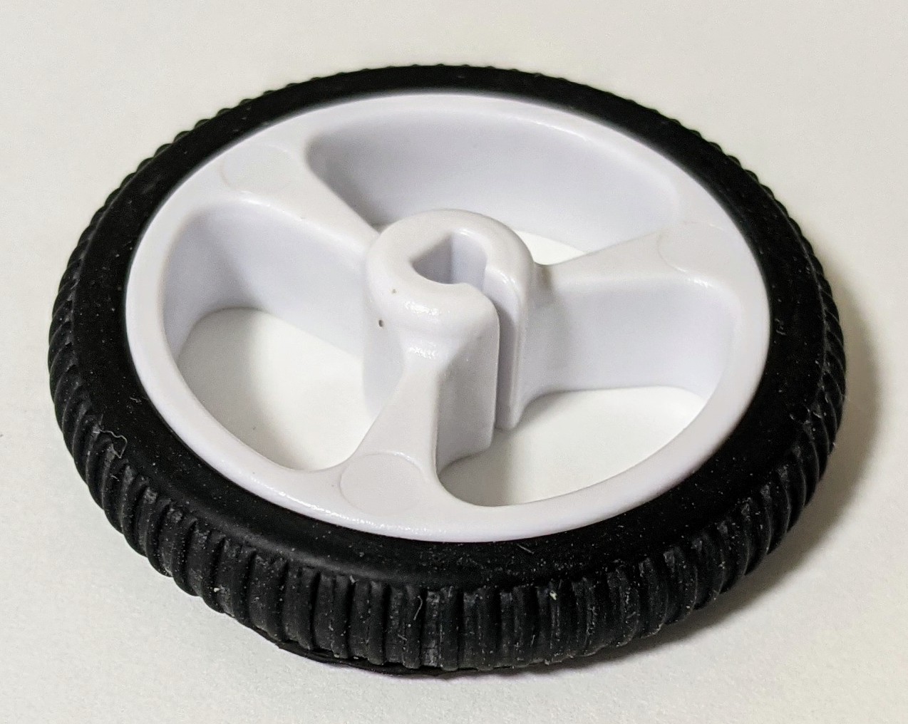
32mm diameter wheels are used.
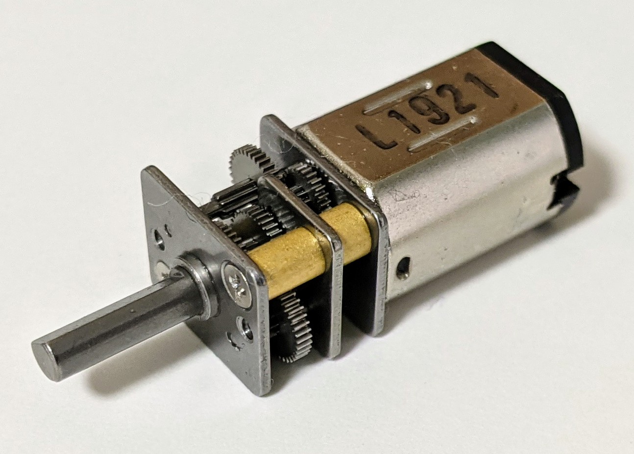
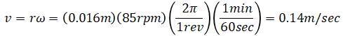
Brushed DC motors are used. Its voltage is rated at 12V and its no-load performance is 85 RPM (at the output shaft of the gear train). This means that when 12V is applied, the robot moves forward 14cm every second:
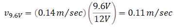
When 9.6V (1.2V * 8) is applied, the robot moves forward at 11cm/sec:
Below is Arduino source code to achieve the motion in the video. It is a state machine with 8 states (forward long, left 90°, forward short, left 90°, forward long, right 90°, forward short, right 90°).
#include <AFMotor.h>


// Pins
const uint8_t BUMPER_BUTTON_LEFT_PIN  = A4;
const uint8_t BUMPER_BUTTON_RIGHT_PIN = A5;


// Motors
// Initialized to RELEASE and speed 0
AF_DCMotor motor_right(1);
AF_DCMotor motor_left(2);
AF_DCMotor motor_fan(3);


// States
// Not using enum because enum is int (16 bits)
const uint8_t STATE_START        = 0;
const uint8_t STATE_GO_STRAIGHT1 = 1;
const uint8_t STATE_TURN_LEFT1   = 2;
const uint8_t STATE_GO_STRAIGHT2 = 3;
const uint8_t STATE_TURN_LEFT2   = 4;
const uint8_t STATE_GO_STRAIGHT3 = 5;
const uint8_t STATE_TURN_RIGHT1  = 6;
const uint8_t STATE_GO_STRAIGHT4 = 7;
const uint8_t STATE_TURN_RIGHT2  = 8;


const int START_PAUSE_TIME_MS   = 1000;
const int GO_STRAIGHT_A_TIME_MS = 4000;
const int GO_STRAIGHT_B_TIME_MS = 1000;
const int TURN_TIME_MS          = 1175;
const int WHEEL_DUTY_FORWARD    =  255;
const int WHEEL_DUTY_BACKWARD   = -255;


uint8_t state = STATE_START;
unsigned long timer_ms = 0;
int wheel_duty_left_prev = 0;
int wheel_duty_right_prev = 0;


void setup()
{
  // Debugging pins
  // Arduino's pin 13 (PB6)
  pinMode(LED_BUILTIN, OUTPUT);

  // Bumper button pins
  pinMode(BUMPER_BUTTON_LEFT_PIN, INPUT_PULLUP);
  pinMode(BUMPER_BUTTON_RIGHT_PIN, INPUT_PULLUP);

  timer_ms = millis();

  set_fan_on(true);
}


void loop()
{
  int wheel_duty_left = 0;
  int wheel_duty_right = 0;

  switch (state)
  {
    default:
    case STATE_START:
      if (millis() - timer_ms > START_PAUSE_TIME_MS)
      {
        timer_ms = millis();
        state = STATE_GO_STRAIGHT1;
      }
      break;

    case STATE_GO_STRAIGHT1:
      if (millis() - timer_ms > GO_STRAIGHT_A_TIME_MS)
      {
        timer_ms = millis();
        state = STATE_TURN_LEFT1;
      }
      else
      {
        wheel_duty_left = WHEEL_DUTY_FORWARD;
        wheel_duty_right = WHEEL_DUTY_FORWARD;
      }
      break;

    case STATE_TURN_LEFT1:
      if (millis() - timer_ms > TURN_TIME_MS)
      {
        timer_ms = millis();
        state = STATE_GO_STRAIGHT2;
      }
      else
      {
        wheel_duty_left = WHEEL_DUTY_BACKWARD;
        wheel_duty_right = WHEEL_DUTY_FORWARD;
      }
      break;

    case STATE_GO_STRAIGHT2:
      if (millis() - timer_ms > GO_STRAIGHT_B_TIME_MS)
      {
        timer_ms = millis();
        state = STATE_TURN_LEFT2;
      }
      else
      {
        wheel_duty_left = WHEEL_DUTY_FORWARD;
        wheel_duty_right = WHEEL_DUTY_FORWARD;
      }
      break;

    case STATE_TURN_LEFT2:
      if (millis() - timer_ms > TURN_TIME_MS)
      {
        timer_ms = millis();
        state = STATE_GO_STRAIGHT3;
      }
      else
      {
        wheel_duty_left = WHEEL_DUTY_BACKWARD;
        wheel_duty_right = WHEEL_DUTY_FORWARD;
      }
      break;

    case STATE_GO_STRAIGHT3:
      if (millis() - timer_ms > GO_STRAIGHT_A_TIME_MS)
      {
        timer_ms = millis();
        state = STATE_TURN_RIGHT1;
      }
      else
      {
        wheel_duty_left = WHEEL_DUTY_FORWARD;
        wheel_duty_right = WHEEL_DUTY_FORWARD;
      }
      break;

    case STATE_TURN_RIGHT1:
      if (millis() - timer_ms > TURN_TIME_MS)
      {
        timer_ms = millis();
        state = STATE_GO_STRAIGHT4;
      }
      else
      {
        wheel_duty_left = WHEEL_DUTY_FORWARD;
        wheel_duty_right = WHEEL_DUTY_BACKWARD;
      }
      break;

    case STATE_GO_STRAIGHT4:
      if (millis() - timer_ms > GO_STRAIGHT_B_TIME_MS)
      {
        timer_ms = millis();
        state = STATE_TURN_RIGHT2;
      }
      else
      {
        wheel_duty_left = WHEEL_DUTY_FORWARD;
        wheel_duty_right = WHEEL_DUTY_FORWARD;
      }
      break;

    case STATE_TURN_RIGHT2:
      if (millis() - timer_ms > TURN_TIME_MS)
      {
        timer_ms = millis();
        state = STATE_GO_STRAIGHT1;
      }
      else
      {
        wheel_duty_left = WHEEL_DUTY_FORWARD;
        wheel_duty_right = WHEEL_DUTY_BACKWARD;
      }
      break;
  }

  if (wheel_duty_left != wheel_duty_left_prev)
  {
    set_wheel_duty(&motor_left, wheel_duty_left);
    wheel_duty_left_prev = wheel_duty_left;
  }

  if (wheel_duty_right != wheel_duty_right_prev)
  {
    set_wheel_duty(&motor_right, wheel_duty_right);
    wheel_duty_right_prev = wheel_duty_right;
  }
}


// duty: -255 to 255 inclusive (else clamped to range)
void set_wheel_duty(AF_DCMotor* motor, int duty)
{
  uint8_t command;
  uint8_t duty_uint8;
  int abs_duty = abs(duty);

  // Convert duty (int) to
  // duty_uint8 (uint8_t: 0 to 255)
  if (abs_duty > 255)
  {
    duty_uint8 = 255;
  }
  else
  {
    duty_uint8 = (uint8_t) abs_duty;
  }

  // Set command (direction) based on the sign of duty
  // At low duty (<10), wheel does not turn so set duty to 0
  if (duty_uint8 < 10)
  {
    duty_uint8 = 0;
    command = BRAKE;
  }
  else
  {
    if (duty > 0)
    {
      command = FORWARD;
    }
    else
    {
      command = BACKWARD;
    }
  }

  // Set speed and direction
  motor->run(command);
  motor->setSpeed(duty_uint8);
}


void set_fan_on(bool is_fan_on)
{
  // Set speed and direction
  if (is_fan_on)
  {
    motor_fan.setSpeed(255);
    motor_fan.run(FORWARD);
  }
  else
  {
    motor_fan.setSpeed(0);
    motor_fan.run(RELEASE);
  }
}
Speed of the motor is proportional to the applied voltage (assuming we apply a constant load and ignore transient response). This means that if supply voltage changes, speed also changes. Voltage differs by battery type, so the speed is affected by what battery is being used. (NiMH battery is 1.2V while alkaline battery is 1.5V). Furthermore, battery voltage changes over time (a fresh alkaline battery starts around 1.6V and decreases to around 1.3V from my experience). This all means that even if the same PWM sequence is sent to the motors, the robot will move and turn differently for every battery and its condition. As a result, this open-loop approach requires tuning the code for every voltage level to achieve the same motion. An improvement would be to add encoders or use stepper motors.
I initially planned on using quadrature encoders (Magnetic Encoder Pair Kit for Micro Metal Gearmotors, 12 CPR, 2.7-18V, Pololu item #: 3081) but then decided not to. This is because Arduino only exposes 2 interrupt pins (PD2 and PD3) but I need 4 (two for each wheel). Furthermore, PD3 is hooked to the motor driver board (Adafruit motor shield v1) to drive PWM signal to the motor.
The alternative method I tried is to use timer interrupt to poll encoder pulses (for all four pins using A0~A3). This method uses a timer interrupt that runs faster than the frequency of the encoder pulses. The interrupt checks whether the encoder signal has changed (high to low or low to high).
The polling method worked, and I was able to capture motor positions. However, there was another issue. Arduino consumed most CPU resource on monitoring encoder ticks. In addition, the motor driver board uses shift register (74HCT595N) to control the direction of the motors (the benefit of this approach is that only 4 Arduino pins are needed to control 8 motor driver pins). The downside of this approach is that it takes time to apply changes to these pins. When the motor overshoots the target angle, it needs to drive backwards. Changing direction of the motor requires time so the control loop is delayed at that instance. The delay is worsened by the encoder CPU overhead. The result is the motor going back and forth just before it is about to stop. I couldn’t find a simple solution to mitigate this issue caused by the delay.
In conclusion, I decided to remove encoders for two reasons. First, one of two Arduino interrupt pins is being used as PWM output. Second, the delay caused by shift registers makes motor control complex. It seems like the motor driver board is not made with encoders in mind.