
Below is an overview of ATmega328P memory summarized from the datasheet. ATmega328P uses harvard architecture where (1) program and (2) data reside in separate memories.
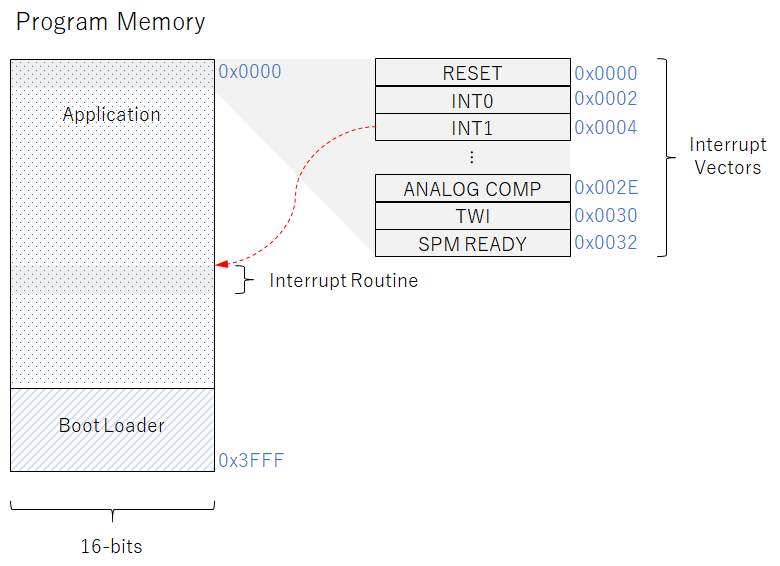
Interrupt table is an array of interrupt vectors. Interrupt vector is a 16-bit memory that contains the address of the corresponding interrupt routine, ISR. All interrupts have a separate interrupt vector.
By default, the interrupt table is stored at the top (lowest address) of the program memory. Interrupts with lower interrupt vector addresses have higher priority. For example, RESET has the highest priority and next is INT0.
The interrupt table can be moved to the start of the boot loader, by
Also referred as: flash memory, program memory space, program flash memory, program flash memory space, in-system reprogrammable flash memory.
Code stored in program memory.
Also referred as: application program, application section.
Code stored in program memory that can execute SPM instruction to write application code to program memory. Arduino uses the boot loader to flash new code without the need for special hardware (i.e. programmer).
Also referred as: boot program, boot flash, boot loader section, BLS, boot loader flash section.
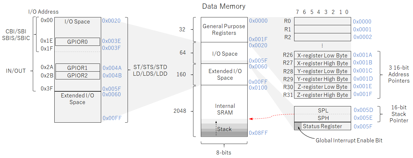
Also referred as: SRAM, data memory space, user data space, data space.
First 32 bytes in data memory.
Also referred as: general purpose working registers, register file, general purpose register file.
64 bytes in data memory for CPU peripheral functions (via control registers), SPI, and other I/O functions.
Interrupt control registers and status register (which contains global interrupt enable bit) are in the I/O space. I/O space also contains three general purpose I/O registers (GPIOR0, GPIOR1, GPIOR2) for storing global variables and status flags.
Restrictions:
Reserved bits should be written to zero if accessed for compatibility with future devices. Reserved I/O memory addresses should not be written.
Also referred as: I/O memory, I/O memory space.
A byte in I/O space that contains information about the result of the most recently executed arithmetic instruction. This information can be used for altering program flow in order to perform conditional operations. Status register is updated after all ALU operations. This can remove the need for using dedicated compare instructions.
Status register is not automatically stored when entering an interrupt routine and restored when returning from an interrupt. This must be handled by user program.
Also referred as: SREG.
7th bit (I-bit) in the status register used for enabling and disabling interrupts.
Interrupt routine is called if
When an interrupt occurs, the hardware
The I-bit can be set and cleared by user program with the SEI and CLI instructions. Setting it enables nested interrupts.
Only ST/STS/STD and LD/LDS/LDD instructions can be used.
Also referred as: data SRAM, internal data SRAM, general data SRAM.
Data allocated in internal SRAM for storing temporary data, local variables, and return addresses after interrupts and subroutine calls. When interrupts and subroutine calls are executed, the return address is stored on the stack. Stack grows from higher to lower memory locations. Stack size is limited by the total SRAM size and the usage of the SRAM.
When an interrupt occurs, the program counter (14-bit memory that contains the address of the currently executing instruction) is pushed onto the stack. Upon return, the program counter is popped back from the stack (2 bytes).
16-bit register in I/O space. Composed of two 8-bit registers, SPL and SPH. Points to (contains the address of) the top of the stack, which is in the data SRAM stack area where the subroutine and interrupt stacks are located.
Instructions:
User program must initialize the stack pointer to 0x08FF (the last address of the internal SRAM) in the reset routine before any subroutine calls are executed or interrupts are executed.
Also referred as: stack pointer register, SP.