2019/06/09
VL53L1X is a distance sensor by ST. This page compares several breakout boards for the VL53L1X sensor. It specifically focuses on I2C and issues associated with voltage level differences.
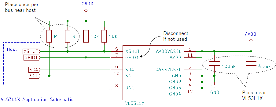
Below is a re-drawing of the application schematic from VL53L1X datasheet. The sensor's nominal voltage is 2.8V and maximum voltage is 3.5V. This poses a problem when connecting Arduino that operates at 5V.
XSHUT is used to shut down the sensor (sensor shuts down when XSHUT is pulled low). GPIO1 can optionally be used as triggers from the sensor when events occur (like measurement done). Datasheet recommends pulling these lines up with 10k resistors. 5V Arduino can use 2.8V XSHUT by open-drain method (set as input by default, set as output-low when needed).
ST has their version of Arduino called STM32 Nucleo. Like Arduino shields, Nucleo boards can be extended by connecting to expansion boards. ST provides an expansion board for VL53L1X called X-NUCLEO-53L1A1. Below is a re-drawing of a section of this expansion board.
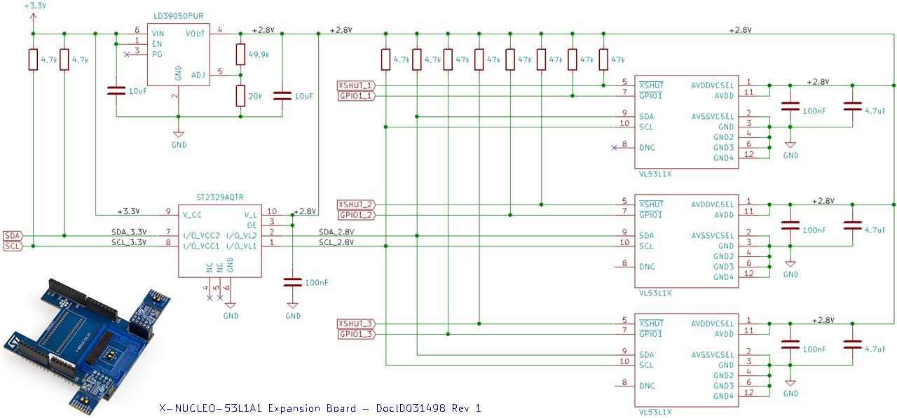
The expansion board contains three VL53L1X sensors. The expansion board is provided with a source voltage of 3.3V. It converts 3.3V to 2.8V for the sensors using LD39050PUR voltage regulator. This voltage regulator can source up to 500mA. VL53L1X datasheet mentions that peak current can reach 40mA so this is well within the limit.
I2C lines are pulled up to 2.8V by 4.7k resistors and they are placed once per bus (not per sensor). Since they operate at 2.8V, a logic level converter (ST2329AQRT) is used to convert betwen 2.8V and 3.3V. Another set of 4.7k pull-up resistors exist on the 3.3V side as well.
XSHUT and GPIO1 lines are pulled up to 2.8V by 47k resistors for each sensor.
Pololu does not disclose part numbers for each of the components in the schematic; however, the structure is similar in that a voltage regulator is used to convert from 5V to 2.8V. Below is a re-drawing of the schematic for VL53L1X Time-of-Flight Distance Sensor Carrier with Voltage Regulator, 400cm Max (Pololu item #: 3415).
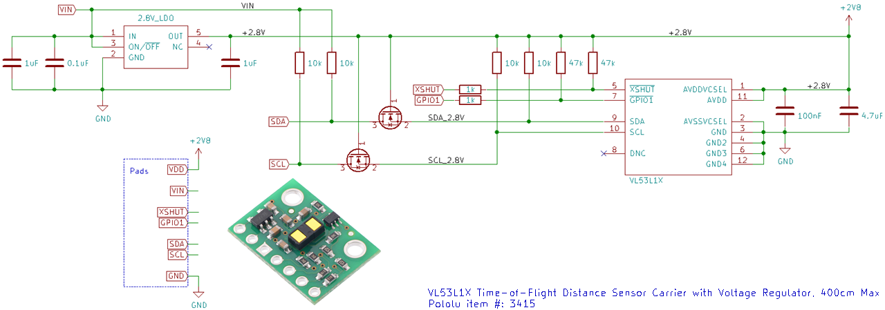
10k pull-up resistors are attached on 2.8V and 5V sides of I2C. This is an issue when multiple VL53L1X sensors are connected in parallel because these 10k resistors will also be connected in parallel and the effective resistance becomes smaller. A way to get around this is to cut off all the 10k resistors on the 5V side of this breakout board except one. This method may improve the situation but it does not address all the issues. When I2C is pulled low, I2C lines on both 5V and 2.8V sides will be connected. As a result, the 10k resistors on 2.8V side will also contribute to the effective resistance. 10k pull-up resistors on the 2.8V side cannot be disconnected due to how level-shifting works.
MOSFETs are used on the I2C lines for 2.8/5V conversion instead of a dedicated IC like in ST's expansion board. This difference is not an issue. The issue is that when multiple boards are connected in parallel, Pololu's board will have a level shifter for each sensor each with a pair of pull-up resistors. ST's board does not have this issue because there is only one level shifter and a single pair of pull-ups to connect all three sensors.
XSHUT and GPIO1 lines are pulled up to 2.8V by 47k resistors like in ST's expansion board. Unlike in ST's board, 1k resistors are connected in series. This may be to limit the current and protect against ESD. GPIO1 is read-only so it could also be a protection against users driving this line by mistake. It could also be a protection for XSHUT being driven above 2.8V by mistake (such as when the microcontroller resets and momentarily pulls this line to 5V). Adafruit's VL53L0X breakout board handles this last case by connecting a 1N4148 diode in series on XSHUT.
SparkFun solves the I2C issue by standardizing all their I2C breakout boards to operate at 3.3V and make the pull-up resistors disconnect-able (they call this Qwiic). Below is a redrawn schematic for SparkFun Distance Sensor Breakout - 4 Meter, VL53L1X (Qwiic) (SEN-14722).
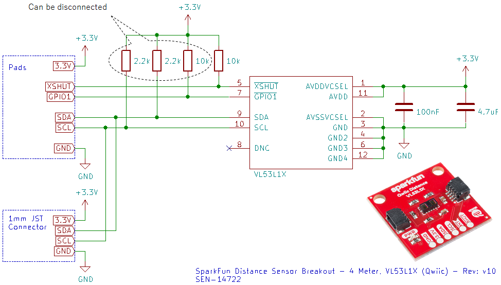
2.2k pull-up resistors are placed on the I2C lines which can be disconnected. XSHUT and GPIO1 lines are pull-ed up by 10k resistors each. The 10k on GPIO1 can also be disconnected.
3.3V is below 3.5V maximum voltage allowed by VL53L1X so this is fine. A minor concern is that SparkFun also standardizes the I2C cable so XSHUT and GPIO1 would have to be connected on separate cables via the pads.
Below is a schematic for Sparkfun Quiic Shield for Arduino (DEV-14352). It mounts on the Arduino to convert I2C from 5V to 3.3V using BSS138 N-channel MOSFETs. 4.7k pull-ups are attached on both 5V and 3.3V sides.
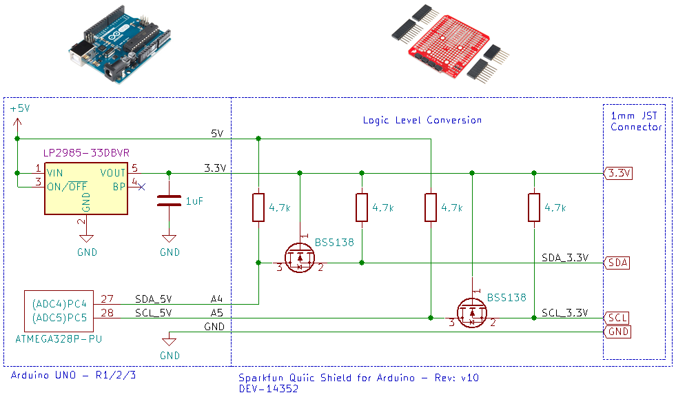
The problem here is that Arduino uses LP2985-33DBVR voltage regulator to step down 5V to 3.3V. This voltage regulator can source up to 150mA. VL53L1X's peak curent can reach 40mA so if 4 of these are connected in parallel, that is already 160mA. There is little safety margin thus such configuration lacks robustness.
SparkFun also has an Arduino that uses a different voltage regulator (AP2112-3.3V) which can source up to 600mA. Below is the schematic for this product, SparkFun RedBoard Qwiic (DEV-15123):
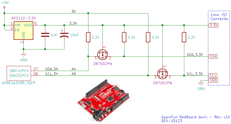
It uses 2N7002PW instead of BSS138 which is a very similar MOSFET. This board uses 2.2k pull-up resistors on both sides of the voltage levels.
One concern with SparkFun's method is that the cables are standardized such that SDA and SCL are next to each other. This may cause spikes in I2C due to crosstalk. Ideally these lines would be placed away from each other (i.e. place GND and 3.3V wires between SDA and SCL). It would be even better to use ribbon cables instead to prevent twisting.
I had an issue where the sensor kept shutting down due to noise on XSHUT wire. The wire was about 40 to 50cm. The issue was solved by connecting a 15nF capacitor from XSHUT to ground at the connector of the sensor breakout board. This is effectively a low pass filter.