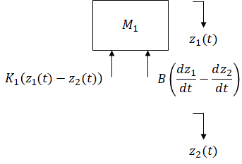
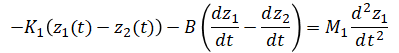
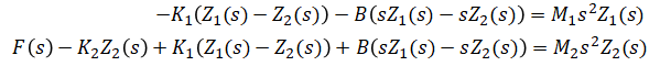
 From above free body diagram,
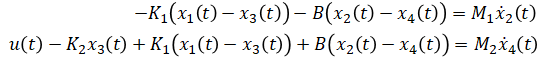
(eq. 1)
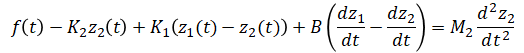
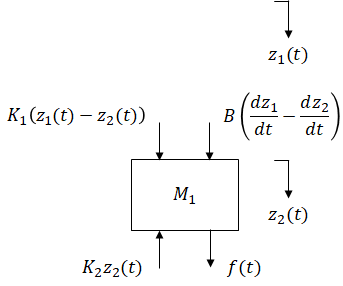 From above free body diagram,
(eq. 2)
Transfer function and state space model are developed for car suspension system shown below. This system is an applied version of the mass spring damper system.
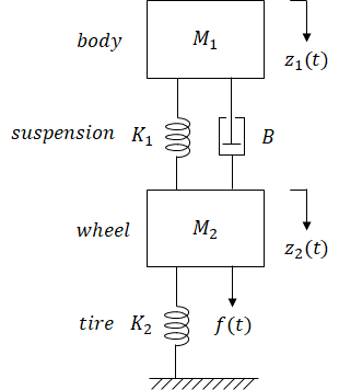
| (input) | f(t) | = | external force applied on tire | |
| (output) | z1(t) | = | displacement of body | unknown |
| z2(t) | = | displacement of wheel | ||
| M1 | = | car body mass | ||
| M2 | = | wheel mass | ||
| K1 | = | suspension spring constant | ||
| K2 | = | tire elastance | ||
| B | = | shock absorber damping coefficient |
2 unknowns so 2 equations are needed.
From above free body diagram,
From above free body diagram,
Laplace transform (eq. 1) and (eq. 2):
Solve for the 2 unknowns:
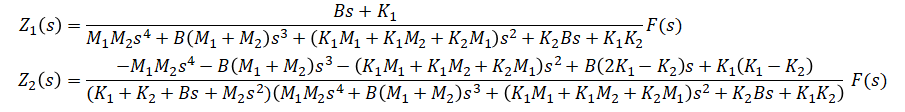
Solve for output/input:

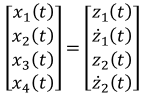
When there is a mass in a system, its position and velocity are commonly chosen as state variables. For this system, position and velocity of both masses and force (input) are sufficient to determine any future ouput value (body's position). For these reasons, position and velocity of both masses are chosen as state variables.
State vector:
Input vector:
Output vector:
Rewrite (eq. 1) and (eq. 2) in these new notations:
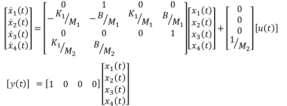
Rearrange equations to express ẋ(t) and y(t) in terms of x(t) and u(t):
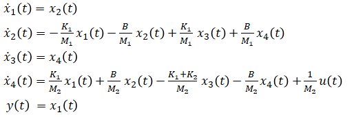
Organize into matrix format:
Note: this system is based off of an example in a textbook[1]. It is modified and extended with additional calculations.
[1]Phillips, Parr (2011) Feedback Control Systems 5th EditionFeedback Control Systems