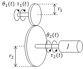
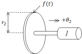
Gears
Transfer function and state space model are developed for torque applied
on a mass through gear train.
| (input) |
τ1(t) |
= |
applied torque |
|
| (output) |
θ1(t) |
= |
top gear angle |
unknowns |
|
τ2(t) |
= |
torque on mass due to τ1 |
|
θ2(t) |
= |
mass rotational position |
|
r1 |
= |
top gear radius |
|
|
r2 |
= |
bottom gear radius |
|
|
J |
= |
inertia |
|
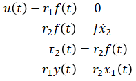
Differential Equation
3 unknowns so 3 equations are needed. During the process of formulating
these equations, a new unknown variable, f(t), is introduced;
therefore, a total of 4 equations are prepared.
-
Newton's 2nd law on top gear
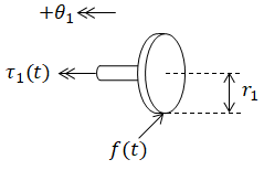 where f(t) is a new unknown variable which corresponds to the force
applied to the top gear due to the bottom gear.
where f(t) is a new unknown variable which corresponds to the force
applied to the top gear due to the bottom gear.
(eq. 1)
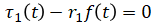
Right hand side of the equation is zero because top gear is massless.
-
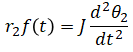
Newton's 2nd law on bottom gear and mass
 Force on top gear is applied on bottom gear with equal but
opposite direction (action-reaction). τ2(t) is not
present because it is the same as the torque due to f(t).
If τ2(t) were used instead, f(t) would not be present.
Force on top gear is applied on bottom gear with equal but
opposite direction (action-reaction). τ2(t) is not
present because it is the same as the torque due to f(t).
If τ2(t) were used instead, f(t) would not be present.
(eq. 2)
-
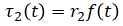
Definition of torque on bottom gear
(eq. 3)
-
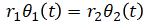
Mechanism of gear (circular distance travelled is same between gears)
(eq. 4)
Transfer Function
Laplace transform (eq. 1), (eq. 2), (eq. 3), (eq. 4):
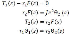
Solve for the 4 unknowns:
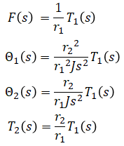
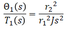
Solve output/input:
(solution)
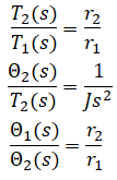
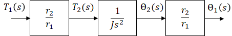
Block Diagram
Transfer functions for block diagram is derived using Laplace equations from
previous section:
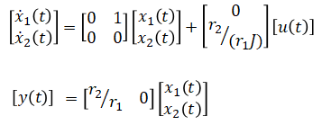
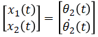
State Space Model
When a mass is present in a system, its position and velocity are commonly
chosen as state variables. Similarly for the rotational case, angle and
angular velocity are chosen for state variables. It can also be noted that
applied torque (input), angle, and angular velocity are sufficient
to determine this system's future angle (output). This confirms the selected state
variables are valid for this system.
State vector:
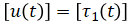
Input vector:
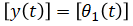
Output vector:
Rewrite (eq. 1), (eq. 2), (eq. 3), (eq. 4) in these new notations:
Rearrange equations to express ẋ(t) and y(t) in
terms of x(t) and u(t):
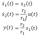
Rearrange in matrix format:
(solution)