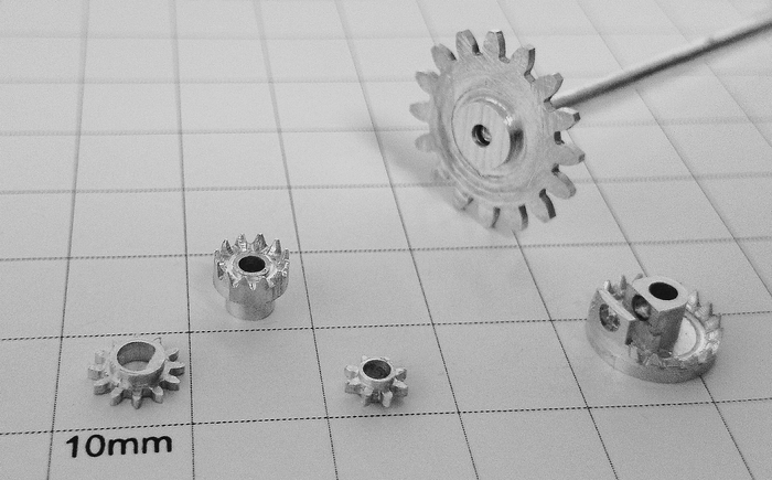
I made aluminum spur gears of module 0.5 and up using hobby CNC. First, I used SOLIDWORKS and involute curve formula to model the part. Then, I used Fusion 360 and KitMill RZ300 to fabricate the part.
Input: Gear Parameters
| Example | ||
|---|---|---|
| Module | m | 0.5 |
| Number of Teeth | N | 8 |
| Pressure Angle | α | 20° |
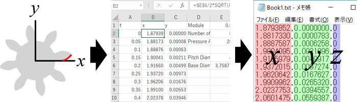
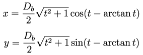
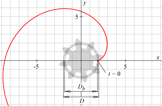
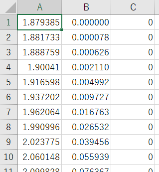
Output: Involute Curve
where
| Pitch Diameter | D = Nm |
| Base Diameter | Db = Dcosα |
Pitch diameter is sometimes called reference diameter. For my example, I used t = 0 to 2 with increment of 0.05. First column is X, second is Y, and third is Z.
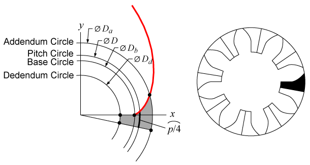
| Tip Diameter | Da = D + 2m |
| Root Diameter | Dd = D − 2.5m |
| Circular Pitch | p = πm |
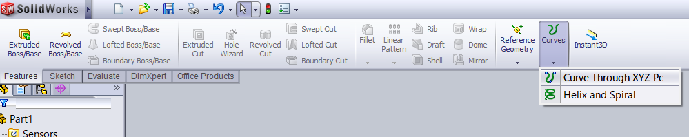
In the following steps, I am using SOLIDWORKS 2009 to import the CSV file and make gear model using it. SOLIDWORKS 2012 and newer and some other CAD softwares support creating curves directly by inputting parametric equations in which case the CSV file is not needed.
Features > Curves > Curve Through XYZ Points
Browse... > Change file type from "Curves (*.sldcrv)" to "Text Files (*.txt) > Open > OK.
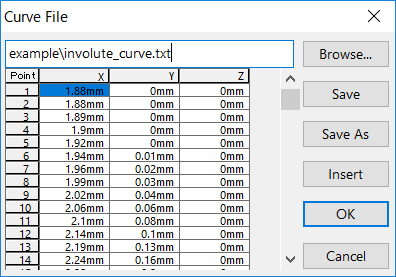
The CSV file extension needs to be ".txt" and not ".csv". If SOLIDWORKS displays error "The data in this file may be invalid." make sure that,
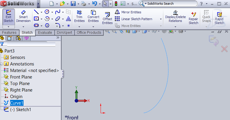
Sketch in Front Plane, select Curve.
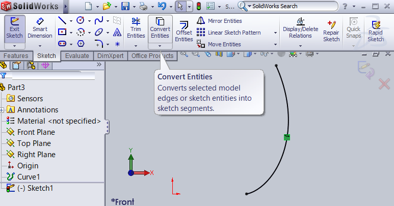
Sketch > Convert Entities.
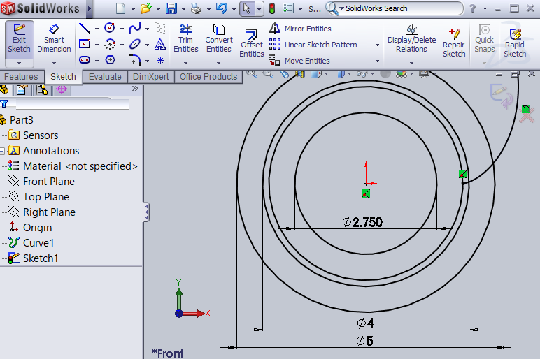
Sketch four circles: dedendum circle, base circle, pitch circle, and addendum circle. Base circle touches the involute curve at t = 0.
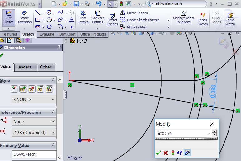
Sketch two straight lines. Dimension quarter pitch arc by clicking the pitch circle and then two points on the sides.
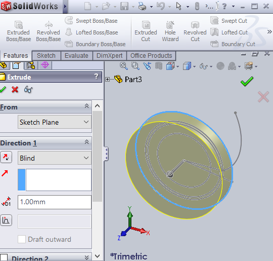
Exit Sketch, Features > Extruded Boss/Base, select tip circle, check.
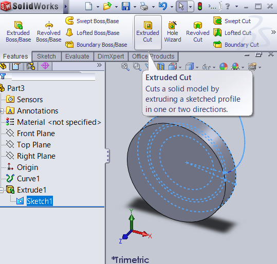
Select Sketch in Extrude, Features > Extruded Cut.
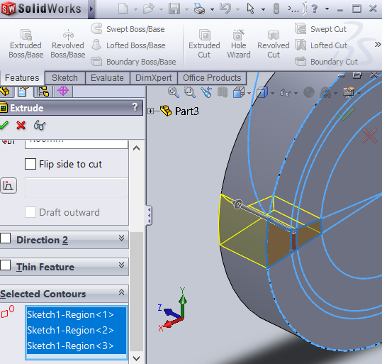
In "Selected Contours", select regions to be removed, check.
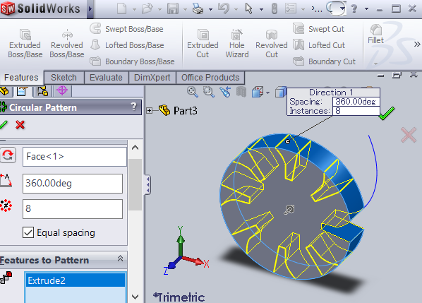
Features > Circular Pattern.
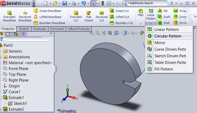
Number of Instances: Number of Teeth (8 in example), Features to Pattern: Extruded Cut feature, check.
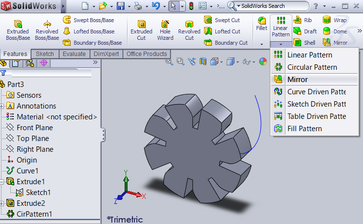
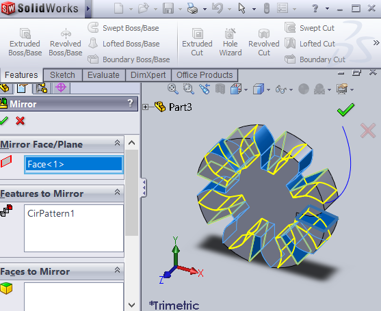
Features > Mirror.
Mirror Face/Plane: flat face in extruded section, Features to Mirror: Circular Pattern feature, check.
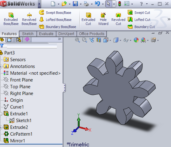
Final model:
I calculate .
I calculate .